What is Amplifiers?
An amplifier, electronic amplifier or (informally) amp is an electronic device that can increase the power of a signal (a time-varying voltage or current). It is a two-port electronic circuit that uses electric power from a power supply to increase the amplitude of a signal applied to its input terminals, producing a proportionally greater amplitude signal at its output. The amount of amplification provided by an amplifier is measured by its gain: the ratio of output voltage, current, or power to input. An amplifier is a circuit that has a power gain greater than one.
An amplifier can either be a separate piece of equipment or an electrical circuit contained within another device. Amplification is fundamental to modern electronics, and amplifiers are widely used in almost all electronic equipment. Amplifiers can be categorized in different ways. One is by the frequency of the electronic signal being amplified. For example, audio amplifiers amplify signals in the audio (sound) range of less than 20 kHz, RF amplifiers amplify frequencies in the radio frequency range between 20 kHz and 300 GHz, and servo amplifiers and instrumentation amplifiers may work with very low frequencies down to direct current. Amplifiers can also be categorized by their physical placement in the signal chain; a preamplifier may precede other signal processing stages, for example.The first practical electrical device which could amplify was the triode vacuum tube, invented in 1906 by Lee De Forest, which led to the first amplifiers around 1912. Today most amplifiers use transistors.

fig1: Operational amplifier
Working of Operational Amplifier:
Operational amplifiers are a fundamental component in electronics. This section focuses on a classic amplifying device, the 741 op-amp.
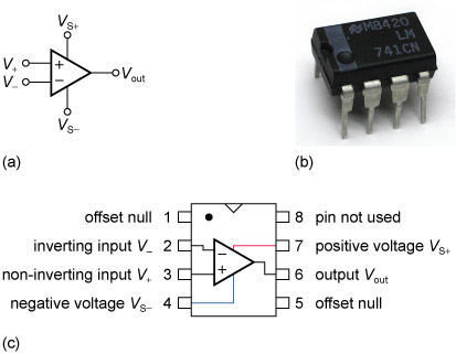
As shown in Figure(a), the op-amp symbol has five terminals. The terminals V+ and V− are used for the input and they control the output, usually as an amplified signal on Vout. The op-amp is built using several resistors and other components called transistors. All these transistors and resistors are packed inside the very small package you can see in Figure (b). A dot and a dent on top of the package are generally used to identify the orientation of the package and therefore the pin number. You can also see these marked on the configuration diagram shown in Figure(c)
Figure 15 (a) Symbol for an op-amp; (b) the 741 op-amp package; (c) top view of an LM741 dual inline package (DIL), showing internal configuration and pin connections
Dual power supplies
On the op-amp symbol, the vertical lines marked VS+ and VS− are very important, since, as already mentioned, they are the op-amp’s connection to a power supply. However, when there is no room for confusion, the two vertical lines leading to the power source (VS+ and VS−) are sometimes omitted from the symbol.
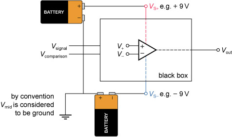
Often a mains dual power supply provides the positive and negative voltages required for an op-amp. Alternatively, you could decide to use batteries to power the op-amp. Since batteries always give a positive voltage, how can they deliver a negative voltage? Figure 2 shows how two batteries can be connected to an op-amp to deliver positive and negative voltages.
